


Όλα τα Προϊόντα
-
 Μπρούνο ΝασιμέντοΣας ευχαριστούμε για τη συνεχή βοήθεια και υποστήριξη σας στην παροχή υψηλής ποιότητας και προσιτών προϊόντων.
 -
 Εχσαν ΣαλμάριΗ ταχεία απάντηση και η επαγγελματική στάση κάνουν τη συνεργασία μας πιο ομαλή!
General Electric DS200DCFBG1B DC Προμήθεια τροφοδοσίας ανατροφοδότησης Κρίσιμο στροβίλου και εφαρμογές κίνησης


| Τόπος καταγωγής | ΗΠΑ |
|---|---|
| Μάρκα | GE |
| Πιστοποίηση | COO |
| Αριθμό μοντέλου | DS200DCFBG1B |
| Ποσότητα παραγγελίας min | 1 |
| Τιμή | $1800 |
| Χρόνος παράδοσης | 5-7 ημέρες |
| Όροι πληρωμής | T/t |
| Δυνατότητα προσφοράς | 999 |
Λεπτομέρειες
| Ονομα | General Electric DS200DCFBG1B DC Προμήθεια τροφοδοσίας ανατροφοδότησης Κρίσιμο στροβίλου και εφαρμογ | Αναγνωριστικό προϊόν | DS200DCFBG1B |
|---|---|---|---|
| Σειρά | Μάρκος V | Εγγύηση | 1 έτος |
| Δίκτυο βάθος/μήκος προϊόντος | 330mm | Καθαρές ύψος προϊόντος | 200 χιλιοστά |
| Καθαρό βάρος προϊόντος | 2 κιλά | Πλάτος καθαρού προϊόντος | 100mm |
| Επισημαίνω | Πίνακας ανατροφοδότησης παροχής ενέργειας συνεχούς ρεύματος DIP Switch SW6,Δελτίο ανατροφοδότησης για τους 12 Jumpers,38 VAC/115 VAC Πίνακας τροφοδοσίας εισόδου |
||
Περιγραφή προϊόντων
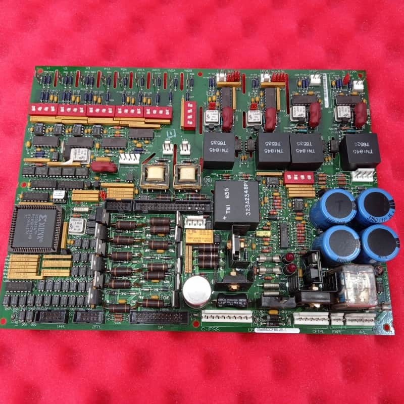
General Electric DS200DCFBG1B Πίνακας Ανατροφοδότησης Τροφοδοσίας DC για Κρίσιμες Εφαρμογές Στροβίλων και Κίνησης
Περιγραφή Προϊόντος:
Η General Electric DS200DCFBG1B είναι ένας πίνακας ανατροφοδότησης τροφοδοσίας DC σχεδιασμένος για κρίσιμες εφαρμογές στροβίλων και κίνησης, συμπεριλαμβανομένων των σειρών EX2000, DC2000 και AC2000. Λειτουργεί ως κεντρικός κόμβος διαχείρισης και παρακολούθησης ισχύος, μετατρέποντας την ισχύ εισόδου από έναν μετασχηματιστή ισχύος ελέγχου σε διάφορες ρυθμιζόμενες τάσεις DC για τη λειτουργία του συστήματος κίνησης και των ανεμιστήρων του περιβλήματος.
Βασικά Χαρακτηριστικά:
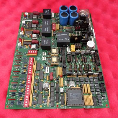
Ο κύριος ρόλος του πίνακα είναι να δημιουργεί και να διανέμει πολλαπλές παροχές ισχύος επιπέδου ελέγχου, συμπεριλαμβανομένων των +5V, ±15V και ±24VDC. Πέρα από τη μετατροπή ισχύος, ενσωματώνει εξελιγμένα κυκλώματα παρακολούθησης που παρακολουθούν βασικές παραμέτρους του συστήματος, όπως το ρεύμα και η τάση του οπλισμού, το ρεύμα πεδίου του κινητήρα και το μέγεθος και η ακολουθία φάσεων της τάσης γραμμής AC. Περιλαμβάνει επίσης τα κυκλώματα οδηγού για τους γεννήτριες παλμών πύλης SCR πεδίου κινητήρα.
Ένα καθοριστικό χαρακτηριστικό του DS200DCFBG1B είναι η χρήση κυκλωμάτων Voltage-Controlled Oscillator (VCO). Αυτά τα κυκλώματα μετατρέπουν κρίσιμες αναλογικές τάσεις εισόδου—από την τάση γέφυρας SCR, την τάση γέφυρας εξόδου και τα σήματα millivolt από τα shunts πεδίου και οπλισμού—σε αναλογικά σήματα συχνότητας (0-500 kHz). Αυτά τα ψηφιακά σήματα συχνότητας μεταδίδονται στη συνέχεια στον κύριο πίνακα ελέγχου SDCC ή LDCC για επεξεργασία, παρέχοντας αξιόπιστη ανατροφοδότηση σχετικά με την κατάσταση λειτουργίας του κινητήρα.
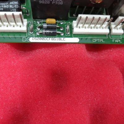
Ο πίνακας είναι εξαιρετικά διαμορφώσιμος μέσω δώδεκα jumpers και επτά διακοπτών DIP, επιτρέποντας επιλογές ειδικές για τον πελάτη, αν και αυτές ρυθμίζονται συνήθως από το εργοστάσιο. Ενσωματώνει ισχυρά χαρακτηριστικά διάγνωσης και προστασίας. Η κατάσταση της ζωτικής σημασίας παροχής +5VDC υποδεικνύεται από το σήμα /PSEN, το οποίο μπορεί να ενεργοποιήσει μια επαναφορά μικροεπεξεργαστή στην κάρτα ελέγχου εάν η τάση δεν είναι ρυθμισμένη. Επιπλέον, ο πίνακας προστατεύεται από ασφάλειες (FU1, FU2, FU3) για τις εξόδους ισχύος του, με σαφείς οπτικές ενδείξεις—LEDs CR51 και CR55 για ασφάλειες DC και ένα φως νέον LT1 για την ασφάλεια AC—για γρήγορη αναγνώριση σφαλμάτων.
![]()
Συνιστώμενα προϊόντα